


对一个密封的光网络单元的冷却设计
日期:2012-06-19
Cooling Design of a Sealed Optical Network Unit (ONU) Enclosure |
|||||||||||||||||||||||||||||||||||||||||||||||||||||||||||||||||||||||||||||||||||||||
|
Mark Hendrix In Fiber in the Loop (FITL) networks, large numbers of Optical Network Units (ONU's) will be deployed that must maintain telecommunications industry standards for reliability while providing for low cost installation and minimal maintenance. These units will carry both conventional telephone traffic, including lifeline service, as well as a host of new broadband services such as video on demand, video teleconferencing, very high speed Internet access, and business data communications. Because ONU's will be placed close to the subscriber's premises, high density packaging is desirable to achieve small, unobtrusive enclosures. These requirements present a significant thermal design challenge. The need for low cost and low maintenance means conventional forced air cooling components, such as fans, which require periodic servicing, are unacceptable. Also, higher density electronic packaging for ONU's carrying both narrowband and broadband services can result in greater heat dissipation per unit package volume than has been traditionally applied in outdoor telecom enclosures. Dissipation levels also are affected by the call traffic and off hook time increases realized by rapid Internet growth. Further complicating thermal design, ONU electronics should be housed in a sealed enclosure per the governing Bellcore documents to prevent moisture ingress in all environments. Consequently, the challenge in ONU thermal design is to use passive cooling techniques that do not add significant cost and size or necessitate maintenance of the unit, but do control device temperatures to levels that support reliability requirements.
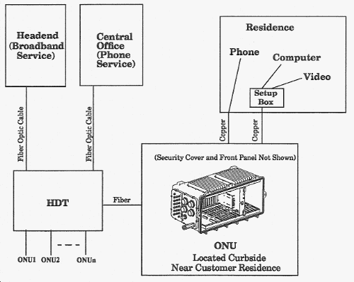
In this paper; two enclosure design concepts that support stated design goals are analyzed and compared. The ONU is one node in the Fujitsu Broadband Network. The ONU accepts both standard telephone service and Broadband service via a fiber optic interface. Data transmitted and received from the fiber optic interface is converted to digital over copper cable in the ONU and distributed directly to customers from the ONU. A high level block diagram of the ONU is shown in Figure 1.
Summary of ONU Thermal and Environmental Requirements Environmental and thermal requirements for the ONU products have been defined by Bellcore GR-950-CORE1, Generic Requirements for Optical Network Enclosures, and by Fujitsu System Engineering For maximum heat dissipation, 75 watts has been assumed for the purposes of this study. Requirements are summarized in Table 1.
Table 1 - ONU Thermal Requirements Summary
Given the above thermal requirements, it is evident that in the sealed ONU enclosure it will be necessary to rely on conduction, radiation, and to a lesser degree natural convection to cool the unit2. The conduction component will include conduction through the relatively stagnant air in the enclosure and through the wall of the enclosure. A primary goal of the ONU thermal design is to satisfy thermal requirements with minimal impact to unit cost and to customers who deploy and maintain the unit. One method of achieving this design goal is to approach the ONU thermal problem from a Systems Engineering perspective. For example, once preliminary FLOTHERMTM analyses indicated potential problems early in the project, it was possible to significantly reduce unit dissipation by using 3.3 Volt devices in the system where possible. Another method of realizing design goals is to implement cooling features that have minimal impact to unit cost and size and no impact to customers. An example of this is application of a black coating within the enclosure to enhance radiation cooling. According to work done by Beckermann and Smith, specially coated interior walls can improve heat transfer significantly through a sealed enclosure3. In fact, Wu and Cengel found that for the case where card guides or other cooling enhancements can-not be used, radiation can be the primary heat transfer mechanism in a sealed enclosure4. A summary of the thermal design options considered for this product are shown in Table 2. The thermal impact of each option was determined by running a separate FLOTHERM case for each design option to determine its effect independently of other options.
Table 2: Thermal Design Options
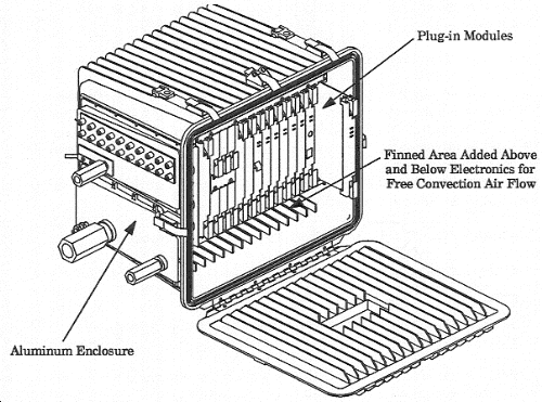
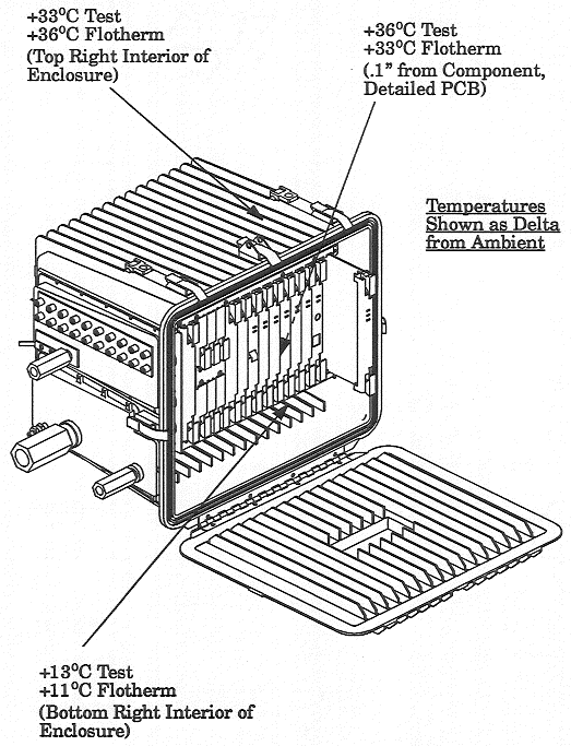
Discussion of Two Enclosure Thermal Design Concepts Given that the ONU must be passively cooled, two basic thermal designs were considered and analyzed. Aluminum Enclosure Design Concept Figure 2 shows a design concept where the enclosure is oversized to allow free convection air flow and to increase the surface area available for cooling fins. The enclosure is entirely cast aluminum and firmed internally and externally to maximize cooling. Per Bellcore requirements, it provides a watertight seal to ambient. The card cage for the Plug-in Modules is a subassembly contained within the enclosure. Thermal analysis and test results are shown in Figures 3-6. This enclosure design concept will be referred to as "Aluminum Enclosure".
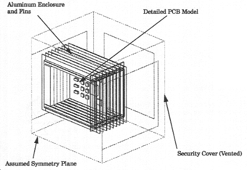
Aluminum Enclosure, Comparison of Test and Analysis Results The FLOTHERM model of this design is actually half of the total assembly as symmetry was assumed about the centerline of the unit. Model array size is 160000 elements. Plug-in Modules were modeled using the PCB option under the "Boundaries" FLOTHERM menu. The aluminum walls of the enclosure were modeled using cuboid blocks. No radiation surfaces were included in the model.
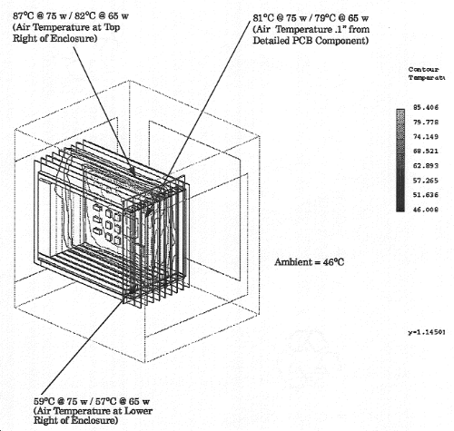
For a 65 watt heat load, Analysis and Test results compare as shown below. Analysis results for the 75 watt case are also shown.
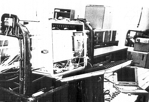
Details of Test Equipment
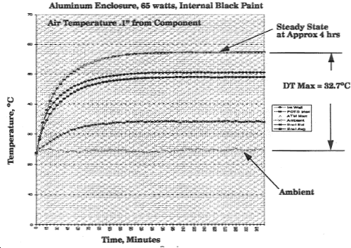
Aluminum Enclosure, Effect of Radiation A second test was conducted on an identical Aluminum Enclosure with the exception that the interior walls of the enclosure were painted flat black to test the potential contribution of radiation. According to Reference 3, radiation can contribute up to 8% of the heat transfer for a sealed enclosure which relies on free convection and conduction cooling Test results show the enclosure with a black interior did have a 10% reduction in temperature rise above ambient Test results are shown in figure 7.
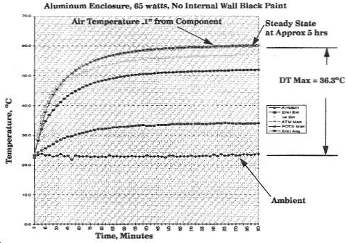
(Aluminum Enclosure, 65W, No Internal Wall Black Paint)
(Aluminum Enclosure, 65W, Internal Black Paint)
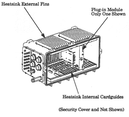
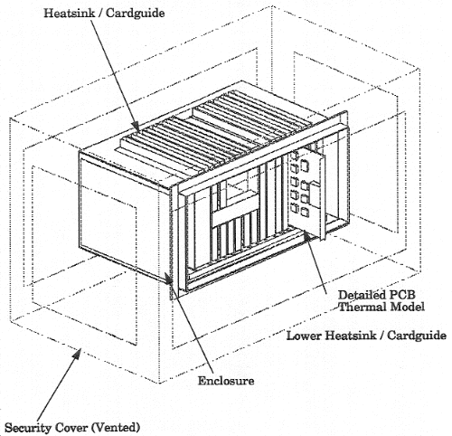
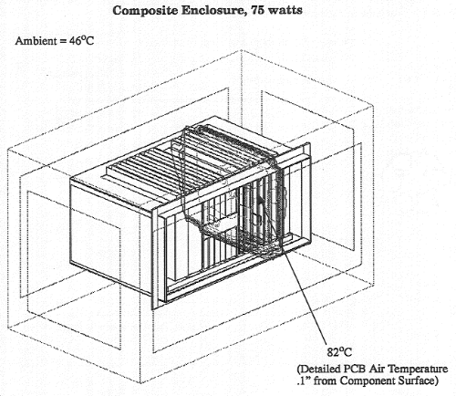
Composite Enclosure Design Concept Figure 8 shows a design concept where card guides for the Plug-in Modules are incorporated into the enclosure walls. The portion of the enclosure walls used for card guides is cast aluminum and finned externally to transfer heat from the card guide side to ambient. The interior surfaces of the enclosure are painted flat black to enhance radiation. The remainder of the enclosure is made of polycarbonate or similar material. Thermal analysis results are shown in figures 9 and 10.
The FLOTHERM model of this design concept consists entirely of cuboid blocks to more accurately represent the conduction contribution of all major solid compounds in the assembly. Model Array size is 479000 cells.
Although there are plans to add a black coating to the enclosure interior walls, radiation surfaces have not yet been included in the model to account the associated increase in heat transfer Therefore, it is expected that the analysis results that follow are conservative. Also, test data is not yet available for this design concept.
Comparison of Two Thermal Design Concepts A comparison of the features and thermal performance of the aluminum composite design concepts is shown in Table 3. Results show thermal performance of the two concepts to be similar. However, because of size and weight advantages, the composite enclosure was chosen for continued design and testing.
References 1. "GR-950-CORE, Generic Requirements for Optical Network Unit (ONU) Closures", Issue 1, December 1994, Bellcore. 2. Beckermann, C., Smith, T. F., and Weber, S. W, "Combined Conduction, Natural Convection, and Radiation Heat Transfer in an Electronic Chassis", Journal Electronic Packaging, December 1991, Vol.113. 3. Beckermann, C., Smith, T.F., "Heat Transfer in an Electronic Enclosure", Technical Report ME-TFS-90-007, Dept of Mechanical Engineering, The University of Iowa, Iowa City, Iowa, 1990. 4. Wu, W, and Cengel, Y.A, "Radiation Heat Exchange Between Electronic Components on a Circuit Board and the Walls of Its Enclosure", Heat Transfer Engineering, Vol 15, No.1, 1994. |

 沪公网安备 31010602003953号