使用FLO/EMC进行电源/接地板的去偶设计
日期:2012-06-19
|
Power/Ground Plane Decoupling Design with FLO/EMC |
|
Author: David Johns FLO/EMC is based on the TLM method that uses a transmission-line network to model electromagnetic field variation in 3D space and time. The TLM method is highly suited to the modeling of mixed fields, wires and circuits. A multi-conductor transmission-line model is integrated into the TLM mesh to enable the analysis of coupling between fields and multi-wires. The coupling is bi-directional; currents and voltages are induced on the wires due to the surrounding field and the wires re-radiate electromagnetic fields. The wire modeling can be used to simulate common-mode and differential mode currents and conducted emissions. Transmission-line models of circuits are also connected into the TLM mesh to model circuit components and voltage/current sources. Therefore, the simulation of a hybrid field-wire-circuit problem is reduced to the solution of a transmission-line network. This is facilitated by an explicit time-stepping algorithm involving the scattering of pulses at discontinuities, where the transmission-lines join, and the connection of pulses between nodes at each time-step. An example of mixed field/circuit analysis is the decoupling of power/ground planes. An electromagnetic field is excited between the planes and decoupling capacitors are used to prevent resonances across the board and to reduce the coupling of noise between various points on the board. Dr. Bruce Archambeault of IBM has done extensive research and development in this area. He has published decoupling examples and provided test measurements [Ref ] The report is available in the EMI modeling section of the Applied Computational Electromagnetics Society (ACES) web site http://aces.ee.olemiss.edu . In this paper, we consider the simulation of the decoupling test structure using FLO/EMC. FLO/EMC Model The test board is a 4-layer board with 2 solid planes in inner layers separated by 40 mils dielectric FR4. The plane size is 10" x 12".
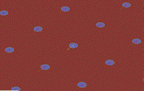
99 decoupling capacitors are located on a 1" pitch across the board. The decoupling capacitors are 0.01mF with a series resistance of 50 mOhms and an inductance of 2nH. In the model, a lumped series C-R circuit is connected to a via-wire located between the power and ground plane. The inductance in the via-wire model is sufficient to model both the component inductance and via inductance. The wire radius may be used to control the via-wire inductance.
Output ports are defined at the center of the board, at one of the corners and on one of the edges. The simulation is used to determine the broad-band coupling or |S21| between the center port and the corner and edge ports. This is achieved by defining wire-ports in the FLO/EMC analysis using 50Ohm port terminations to model the SMA connectors used in the test. Simulation Results 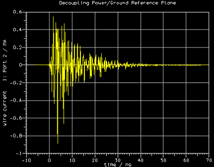
Time-Domain Response of Current at Corner Port
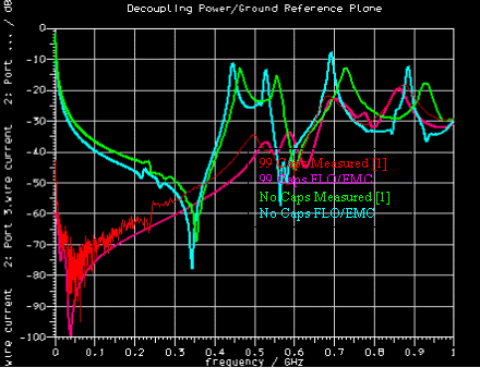
|S21| Center to Corner
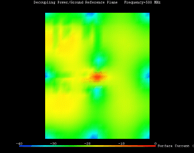
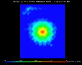
The |S21| results show good correlation with the test results published in [1]. Valuable information can be obtained by viewing the current and field in the board. Below we show the results at 500 MHz and the effect of the decoupling capacitors is clearly seen. The field/current distributions help the design engineer decide the optimal locations for the capacitors.
Surface Current on Ground Plane (No Capacitors)
Electric Field between the Power/Ground Planes (No Capacitors)
Surface Current on Ground Plane (99 Capacitors)
Electric Field between the Power/Ground Planes (99 Capacitors)
Conclusions
The model and results shown in this case study demonstrate the suitability of FLO/EMC to simulate power/ground plane decoupling problems. FLO/EMC can be used to determine the density, optimal placement and values of decoupling capacitors required to suppress electromagnetic noise in the multi-layer board. The parasitics of the capacitor components can be included in the electromagnetic analysis and the resulting reduction in decoupling performance investigated over a wide-band. The frequency range of the analysis is 0 to 1.0 GHz. This can be extended to higher frequencies by making the TLM mesh finer. FLO/EMC uses 425k cells requiring 418 Mbytes RAM. The simulation computes 445k time-steps and takes 45 minutes on a 700 MHz PIII computer. Acknowledgement
We wish to thank Dr. Archambeault for suggesting the decoupling analysis problem and valuable technical discussions. |






 沪公网安备 31010602003953号