导弹系统中的电子设备的热分析
日期:2012-06-19
| Thermal Analysis of Electronics in a Missile System |
|
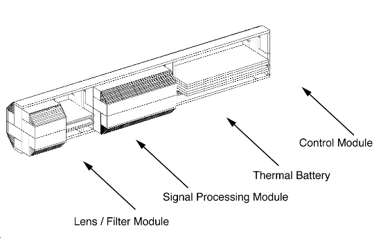
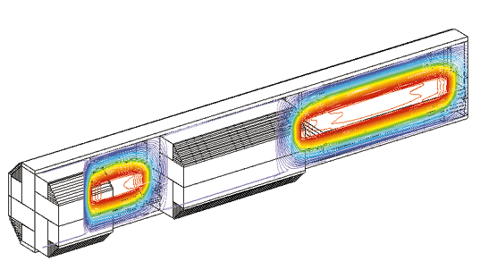
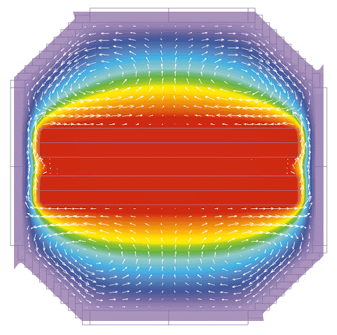
Thermal analysis of electronics in a missile system presents particular problems. The enclosure is cylindrical in shape, but the heat sources (the electronic components) are rectangular. The use of a cylindrical coordinate system would make it easier to model the tube, but very difficult to model the electronics, and vice-versa. In FLOTHERM the entire problem is represented on a simple Cartesian grid system. The cylindrical tube wall is represented by a series of overlapping cuboid elements (see figures 1 and 3). The area of overlap between the cuboid elements provides the correct conduction path in the tube wall. This stairstep approach is obviously not appropriate for calculating the heat transfer on the outside of the tube, where high-speed aerodynamic effects are important. However, this simple approach correctly accounts for all the important heat-transfer mechanisms inside the tube, which are of primary concern in this case. The use of a Cartesian grid simplifies detailed modeling near the heat sources. The same approach can be used for any situation where electronic components are housed in cylindrical or curvilinear shaped enclosures (e.g. periscope tubes, handheld devices, etc.). Figure 1 shows the main elements of the problem. The outer tube is 1mm thick stainless steel. The PCBs in the Control Module are modeled as two connected blocks with thermal properties of 96% Alumina and Epoxy. Each layer is 0.04 inches thick. The heat sources from the components within the Control Module are represented as planar sources directed into the surface of the board. An interface resistance is added between the blocks to represent a thin layer of die-attach epoxy. The Signal Processing Module is modeled in an equivalent manner, except that the Alumina substrate is 0.025 inches thick. The Thermal Battery is modeled as an octagonal volume with a fixed temperature of 60. The lens filter module provides no thermal contribution and is simply modeled as an adiabatic block.
In this case, the analysis is for steady-state conditions. However, the analysis is easily extended to transient to include:
This example illustrates how thermal models of complex geometries consisting of cylindrical or curvilinear enclosures containing rectilinear heat sources can be produced in a simple and efficient way using FLOTHERM. |


 沪公网安备 31010602003953号