航空电子设备的强制对流冷却
日期:2012-06-19
Forced convection cooling of airborne electronics
Yannick Assouad,
Thermal and Mechanical Analysis Group Thomson-CSF Radars & Contre-Mesures
 |
Fin pitch = 25.01 per in = 985 per m Plate spacing, b = 0.200 in = 5.08 x 10⁻³ m Fin Length = 0.111 in = 2.8 x 10⁻³ m Flow passage hydraulic diameter 4rh = 0.004905 ft = 1.50 x 10⁻³ m Fin metal thickness = 0.004 in = 0.102 x 10⁻³ m Total heat transfer area/volume between plates, ?= 719.4 ft2 / ft3 = 2,360 m2 / m3 Fin area / total area = 0.881 |
Introduction
Thermal control has always been an important part of the design criteria for airborne electronics on account of the following two characteristics:
- the airborne environment is harsh, with ambient air temperatures ranging from -55 to 100 癈 or more,
- weight and volume constraints dictate that the design be more compact than those created for commercial electronics.
In the seventies, it was discovered that natural convection alone in the airborne environment was unsuitable for keeping the component junction temperatures at reasonable levels. As air is widely available on aircraft, thermal engineers naturally orientated more of their designs towards forced convection.
Design goals
There are two objectives in the thermal control of airborne electronics:
- to provide a thermal environment which allows the electronic components to perform at their specified level. This was not really a problem two years ago when military components were readily available. Today, however, military components have become scarce and airborne equipment must now be designed with industrial components or COTS (Components Off The Shelves).
To meet our goal, the component case temperature must be:
![]() Tcase < 85癈 for industrial components,
Tcase < 85癈 for industrial components,
![]() Tcase < 70癈 for COTS
Tcase < 70癈 for COTS
- to provide a warranty by applying the following criteria for the component junction temperature:
![]() Tjunction < 90癈 for a maximum junction temperature (Tjunction max) of 150癈 given by the component manufacturer, for normal conditions covering 90 to 95% of the flights,
Tjunction < 90癈 for a maximum junction temperature (Tjunction max) of 150癈 given by the component manufacturer, for normal conditions covering 90 to 95% of the flights,
![]() Tjunction < Tjunction max - 25癈 for extreme flight conditions.
Tjunction < Tjunction max - 25癈 for extreme flight conditions.
Design methodology
To design an air cooling circuit, the engineer must consider carefully the following parameters.
Electronic circuit board power dissipation surface density: For power dissipation densities less than 500 W/m2 (0.05 W/cm2) on the surface of a fully populated PCB (Printed Circuit Board), free convection is favored. For power dissipation densities greater than 4000 W/m2 (0.4 W/cm2), forced air cooling should not be used, regardless of the velocity that can be obtained, and more efficient cooling techniques (heat pipes, liquid cooling, boiling) should be considered [1]. This upper limit for forced air cooling is dictated by the fact that heat sinks cannot be used on the circuits due to the lack of space in avionics racks. The boards are designed for a minimum pitch. In between these two limits, forced convection is well suited.
Environment: Although air is readily available on an aircraft, different qualities of air do exist and may determine differences in designs.
Pressurized bay: this is the most favorable case because forced air cooling can be obtained using a fan. The designer can:
- calculate a flowrate Qfrom the electronic equipment's overall power dissipation, and air temperature increase through the equipment, using the following formula:
where p and cp are the air specific mass and specific heat.
-
calculate the equipment pressure drop
 P at flowrate Q:
-
select a fan from a fan manufacturer's catalogue using these two characteristics (Q,
 P).
P).
It is important to check that the air velocity obtained on each circuit provides a convective heat transfer coefficient sufficient to limit the temperature gradient between the components and the air. If not, it will be necessary to check the uniformity of air flow distribution on each board. Local heat sinks can also be used on high power components, if space is available. Alternatively, a more powerful fan can be selected.
Depressurized bay: the decrease of air density when the altitude increases must be taken into account when choosing the fan. It is important to check that the component temperatures will remain within the prescribed limits.
Defining, at atmospheric pressure,
- Qv0: fan volume flowrate
- Qm0: fan mass flowrate
- P0: pressure delivered by the fan
-
 P0: pressure drop of the electronic equipment at Qv0,
 -
 0: air density;
and at altitude z which corresponds to a static pressure Pstat, - Qv: fan volume flowrate,
- Qm: fan mass flowrate,
- P: pressure delivered by the fan,
-
 P: pressure drop of the electronic equipment at Qv,
 -
 : air density, then the following relations apply:
Qm/Qm0=
which means that the mass flowrate will decrease at the same rate as air density, which in turn will yield a greater air temperature increase going through the electronic equipment. This may not be compensated by the static air temperature decrease which occurs with altitude.
We also have:
which means that the pressure delivered by the fan will decrease but will be compensated by the decrease of pressure loss at Qv. The motor glide may change with air density, which will have an impact on the fan flowrate and delivered pressure and thus sh should not be neglected, especially if the altitude range is wide.
Then the design steps are the same as those applied to the previous case.
Aircraft Environment Control System (ECS) air: aboard an aircraft, especially fighter aircraft, there exists an ECS which can provide cool air to electronic equipment. Flowrate and pressure can generally be provided in sufficient quantities to cool electronics efficiently.
This type of forced convection cooling creates problems due to air pollution. This air contains particles such as dust, sand, metals and fluid droplets, typically oil, kerosene and liquid water.
It is therefore unwise to pass this air directly over the electronic components due to the risk of decreased reliability from micro short-circuits, abrasion or chemical degradation of the components.
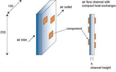
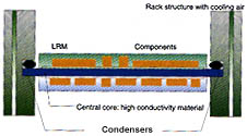
Electronic equipment should be designed to avoid contact between the components and the pollutants: air is passed through cold plates installed either directly at the board level (see Figure 1) or at the rack level (see Figures 2 and 3).
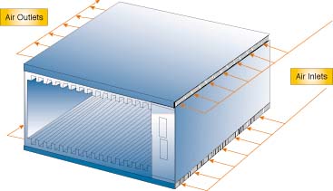
Figure 1 shows a compact finned cold plate embedded in a double sided circuit. This is an Air Flow Through module (AFT). The heat generated by the electronic components is transferred first by conduction through the board and then by forced air convection. The forced convection heat transfer coefficient is enhanced by the compact fins of the cold plate. Air is usually directed along the width of the circuit boards in order to limit the pressure drop.
Figure 2 shows a rack which has two cold plates cooled by ECS air. The rack includes circuit boards which are cooled by conduction enhanced by a metal (generally aluminum or copper) plate in contact with the wall cold plates through thermal clamps located on each side of the circuit as shown on Figure 3.
Design tools
Two kinds of design tools are required for the analysis of the forced convection cooling methods described in the previous paragraphs:
- a CFD code to calculate pressure drops, air PCBs or in finned cold plates,
- a thermal analysis code to check that component junction and/or case temperatures are within the prescribed limits when cooled coefficient given by the CFD code.
Iterations are generally necessary between the two types of calculations to converge to a satisfactory solution.
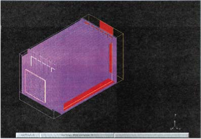
CFD calculations: Figure 4 shows an example of a Flotherm CFD calculation for six fan cooled PCBs. In this case, the CFD calculation has three purposes:
- to aid in fan selection, calculating the pressure drop for the prescribed flowrate;
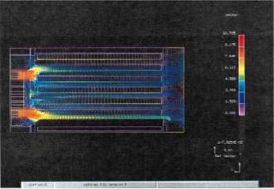
- to design the air distribution and collecting chambers, so that the air velocity is uniform for each PCB, assuming approximately uniform power dissipation. Figure 5 shows the upper view of the rack and the air distribution among the five PCB's;
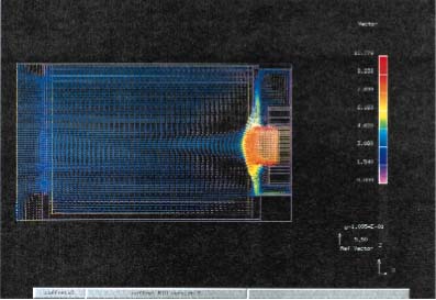
- to get air velocity and air temperature on each PCB, which will constitute the boundary conditions for the thermal analysis of each circuit, Figure 6 shows the air velocity distribution on one of the circuit boards.
Thermal analysis: Once the boundary conditions have been obtained from the CFD calculation, a thermal analysis may be performed on any part of the circuit. However, two other essential points must be considered:
- the convective heat transfer coefficient on the component faces and on the PCB must be evaluated. Fully populated circuits are very complex objects from a fluid dynamics point of view, which explains why literature correlations, classically used to estimate convective heat transfer coefficients fail to give correct values for electronic cooling. The heat transfer coefficient is usually underestimated using these of correlations or CFD calculations; Thomson-CSF Radars & Contre-Mesures has developed its own correlations from experiments, over a ten year span.
- Compact thermal models for each component populating the PCB are required because, detailed models of each component would take hours or days to run on a computer; the European project DELPHI methodology and results [2] have helped considerably to increase Thomson-CSF and other partners ability to create reliable compact models.
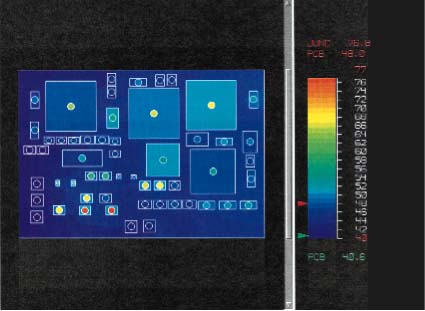
Figure 7 gives an example of the thermal analysis performed on one of the circuits of the previous rack, using a board level thermal analysis tool, VTAT (Visula Thermal Analysis Tool) of Zuken Redac.
Cooling method summarized
Based on previous work conducted within Thomson-CSF - including both CFD calculations and thermal analysis checked with experiments - a ranking of the three different types of forced convection described at the beginning i.e. direct air forced convection, AFT and conduction cooled modules in an air cooled rack, can be created.
The ranking is as follows:
1. Direct air forced convection on components may authorize power dissipation densities on a fully populated board, up to 3000 W/m2, with an air velocity in the range of 5 m/s. This type of design requires non-polluted air and a powerful fan on account of the high velocity of 5 m/s which will generate high pressure drops.
2. An AFT may allow power densities up to 3000 W/m2 or more, but with a very large pressure drop penalty. For 3000 W/m2, the pressure drop will be in the order of 5 mbar for a 100 mm wide module which yields, for a 200 mm wide classical module, a total pressure drop of 10 mbar, not accounting for the distribution and collecting air chambers [1].
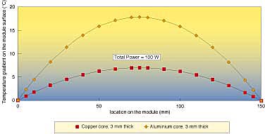
3. Conduction cooled modules in an air cooled rack are limited to power densities up to 1500 W/m2, due to the parabolic temperature gradient from conduction in the metal plate embedded in the PCB (see Figure 8).
Conclusion
Thermal control of airborne electronics has allowed the development of the advanced air forced convection cooling techniques which have been presented here. Furthermore, increases in power dissipation densities combined with the constraint of lightness will require the investigation of even more efficient cooling techniques such as liquid flow through modules, flat heat pipes and direct evaporation. The two latter techniques still require improvements before use on board aircraft on account of their sensitivity to stressed mechanical environment.


 沪公网安备 31010602003953号