


EMC中的计算电磁学
日期:2012-06-20
Computational Electromagnetics
|
|
Author: Paul Duxbury, Flomerics Ltd. How many times have you gone to the EMC test laboratory only to find that your product is exceeding the radiated emissions limits? Once you have discovered that your product is failing, you are then left with the onerous task of trying to determine why this failure has occurred and attempting to rectify the problem. What would you give to be able to reduce the number of test cycles for a particular product, lets say by half or even better? Wouldn't it be even better if this scenario didn't occur at all and the sample passed first time? If this can be achieved, the benefits are obvious, a reduction in costs and also, perhaps more importantly, a shorter time to market. Is the above a dream? Well, perhaps it is but if you were to use simulation tools during the design process hopefully you would be part way to making it a reality. Even today, several years after the introduction of the EMC Directive within Europe, many companies both large and small, still leave EMC till the end of the design cycle, considering it to be a test and measurement discipline. Generally, once a product has gone to the test laboratory, there is very little room, in terms of time, cost and physical space, left for the EMC engineer to play with to try and improve the products performance. So how about trying to improve the performance upfront, before you go to test, in fact before you have even built the first prototype? This is now becoming much more of a possibility thanks to the recent advances which have been made in the field of computational electromagnetic modeling. While only a few years ago, such tools were the preserve of the academic and research environments, they are now becoming more widely used in the commercial world. Simulation is now used throughout the electronics design cycle, examining issues as diverse as mechanical and electrical stress, cooling and signal integrity, so why not EMC?
Why is design analysis important?
Over the past few years, the computational power of the typical PC microprocessor has increased several times over, and no doubt will continue to do so. They contain more and more transistors, switching faster and faster and hence, the power dissipated from them has also increased. Obviously, if the components within a system are getting hotter, there is also a need for improved cooling. The simplest way to improve the cooling is to open up the enclosure, i.e. increase the size of the ventilation holes. However, this could result in an increase in the level of emissions that can be radiated from the enclosure, particularly with the increasing clock frequencies now being used. So, the thermal engineer wants to place as many holes as he can around the enclosure to keep the system as cool as possible but, the EMC engineer on the other hand, would like to place the system in a fully sealed box which has no holes in it. So we are left with a design conflict, thermal verses EMC. For many years, through the use of tools such as FLOTHERM, the thermal engineer has had the ability to analyze the impact of design changes on the thermal performance of a system before it has been built but, the EMC engineer has had to wait to get a physical prototype into the test lab. Not anymore, tools such as FLO/EMC are leading an evolution in electromagnetic analysis, allowing the EMC engineer to analyze design issues much earlier in the design cycle.
Using EMC analysis in Design
One area of product design that can affect both the thermal and EM performance of a system is that of heatsinks. These are predominately a thermal component and are designed as such but their electromagnetic characteristics are important and, should also be considered as part of the design process. With the increasing clock frequencies of microprocessors, heatsinks now have a much greater probability of acting as antennas, radiating the energy from the processor into the surrounding region. This radiation can then couple into adjacent components and tracks eventually finding its way to the outside world. Additionally, the recent proliferation of wireless technologies in electronic equipment, an issue we will examine in a moment, means there is also a potential for interaction between the heatsink and the antenna. The heatsink shown in figure 1, is modeled in two configurations, one floating from and one grounded to the ground plane. As can be seen from the frequency domain results (figure 2), when the heatsink is floating, there is a resonant component at approximately 2.45 GHz, which correlates with the wireless application frequency.
Therefore, if this heatsink was installed in a laptop PC, for example, which was also wireless application enabled, there is the potential for interaction between the heatsink and the antenna. By visualizing the surface current and RF field distribution on and around the heatsink (figure 3), it is possible to define some potential grounding strategies to try and reduce the radiation from the heatsink. In this example wires, or ground pins, were connected between the heatsink and the ground plane at each corner and the center of each edge of the heatsink. As can be seen in figure 2, this results in a dramatic change in the level of radiation, although not at the frequency of interest. 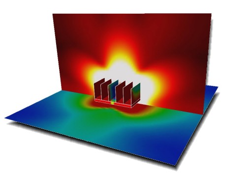 Figure 3; Surface Current and RF Field Distribution for the Floating Heatsink at 2.45 GHz The analysis of system components, such as the heatsink example described above, allows the EMC engineer to make design decisions early in the design process. However, when these components are placed inside an enclosure, the resonant characteristics of the enclosure will affect the resultant electromagnetic characteristics. For example, lets assume that you have a box which has a push fit front panel, connecting to the main chassis in the four corners. Around the edge of the front panel therefore, there are some very long thin slots. What effect do these slots have on the frequencies which can radiate from the box or it will be susceptible to? Maybe not very much but, if they resonate at or close to the frequency of a clock or harmonic of, the effect of the slots on the overall system performance could be huge. Also, as more features are placed into the box, the number of frequencies that the box and it contents will support will increase. So, how does this relate to systems which have integrated antennas? We have already examined how the resonant characteristics of a heatsink could interact with the antenna and, exactly the same is true from the point of view of the enclosure. However, there is also one more issue to consider, could the performance of the antenna be disturbed by the presence of the enclosure? In a recent study undertaken by Flomerics and GE Plastics, it was clearly shown that even a plastic enclosure could significantly affect the performance of an integrated antenna. Generally, antennas are designed and simulated in a free space environment, which gives the 'unloaded' characteristics of the antenna over the desired frequency band. In the study, a typical wireless application antenna, designed to operate at around 2.45 GHz, was simulated in free space, and its return loss calculated, as shown in figure 4. The antenna was then loaded with a 3 mm thick block of plastic to represent the effect of the enclosure material on the antenna performance. The result was quite startling as can be seen in figure 5. By placing the plastic on top of the antenna, the frequency response has been significantly altered, such that the minimum return loss is now approximately 300 MHz lower in frequency. The resulting effect is that the antenna is no longer effective at its operating frequency of 2.45 GHz.
Figure 4; Return Loss for Antenna Simulated in Free Space
Figure 5; Return Loss for Antenna Simulated with Plastic Loading
Conclusions
While EM simulation will probably never negate the need for actual testing, it can be used to identify, analyze and rectify potential design problems before you have a physical prototype and definitely before you go near to a test chamber. The biggest benefit for the user of simulation software, be it for thermal or electromagnetic analysis, is by using it in the early product design stages, where there is still the ability to make design changes. Analysis of this type is quick, easy and substantially more cost effective to perform in a virtual prototyping environment than by manufacturing and testing numerous physical prototypes. Paul Duxbury is a Senior EM Engineer for Flomerics Ltd. who produce thermal and electromagnetic analysis software for the electronics industry and he can be contacted by phone on 020 8941 8810 or by email at paul.duxbury@flomerics.co.uk. |


 沪公网安备 31010602003953号