PQFP + Heatsink = ?
日期:2012-06-20
PQFP + Heatsink = ? |
|
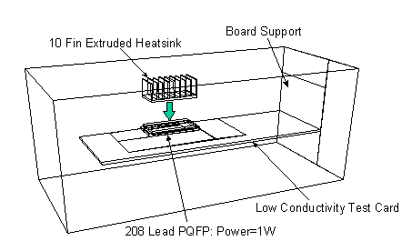
The calculation is based on a 208L PQFP similar (but not identical) to the package used in the JEDEC JC15.1 Still Air Round Robin. The board is a low conductivity test board (JEDEC Standard JESD15_3) and it is mounted in a horizontal configuration.
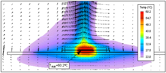
With the power set to 1W, we get the results shown in Figure 2 with a junction temperature Tj of 60.2 C (or (Theta)ja = 40.2 C/W). Now, what happens if I add a nice big heatsink - in this case, an extruded Aluminum heatsink with 10 fins? Figure 3 shows that, as you'd expect, Tj drops to 42.3C ((Theta)ja = 22.3C/W). Obviously all that extra surface area is really helping.

But now lets look a little more closely at what's happening inside the component. We know that, for this type of package without a heatsink, the majority of the heat passes through to the board through the leads (see, for example, Application Note #102). In fact, for this package in this configuration without a heatsink, the proportion is about 65%. With the heatsink on top, we would expect to see a much greater proportion go through the top and thus less through the leads. But, if we use FLOTHERM mean flow regions to determine the heat flux through the leads, we find that the proportion has only dropped to about 58% (Figure 4) - not a very great effect.
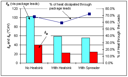
Let's look at it in a different way. Given the power flux through the leads, and the temperature of the die and the board, we can calculate an effective thermal resistance for the conduction path from the die to the board - let's call it (Theta)jb. Without a heatsink, the junction to board thermal resistance is about 100C/W. With the heatsink in place, the junction to board thermal resistance drops to 58C/W. How is the heatsink changing the thermal characteristics of the component?
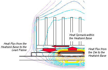
Natural Convection Close up of the Temperatures in the Package Look a little more closely at the temperature contours within the package when the heatsink is on top. Figure 5 is a close-up of the package which shows that, at the center of the package, the temperature gradient drives heat from the die into the heatsink. However, towards the edge of the package, the temperature gradient is reversed and heat is conducted from the heatsink base into the package itself and from there through the lead frame into board. In effect, the heatsink base provides a conduction path parallel to the lead frame thus reducing the junction to board thermal resistance.
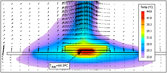
Finally, let's try something radical. Let's cut off all of the fins from the heatsink and simply attach the heatsink base to the top of the package! A conventional analysis using a databook value for (Theta)jc and Heatsink Thermal resistance would suggest that we'd get slightly poorer performance than the bare package (we are adding a little thermal resistance to the top but leaving the exposed area unchanged). However, when we run the calculations, we find that the performance is considerably better than the bare package, and very little worse than the case with the heatsink (Tj = 44.9 C or (Theta)ja = 24.9C/W).
Credit where credit's due: I am indebted to Tiao Zhou of SGS Thomson for suggesting this little study - something that I'd never even thought about! |


 沪公网安备 31010602003953号