|
Pierre Kil
Thermal Engineer, Philips CFT
P0 Box 218
5600 MD Eindhoven, Netherlands
Tel: +31 40 2733049
Fax: +31 40 2735996
E-mail: kil_pe@cft.philips.nl
Abstract
Within Philips Audio - Vienna a new audio set was being developed. The demand for a reduced time-to-market, made it impossible to carry out extensive measurements on prototypes. Therefore, predictive modelling was used to analyse the thermal behaviour of the set, in an early phase of the design. At CFT, a Flotherm system model was developed which tried to meet the demands, set by the Audio organisation. With the model, reliable conclusions had to be drawn. Moreover, the first conclusions had to be drawn within two weeks.
Knowing that the same type of reliable and quick predictive modelling could be asked for on a more regular base, a library of compact models was set up. Thermal requirements were partly redefined, creating mare realistic specifications. From the library of compact models, a system model of the complete set was constructed. Extra attention was paid to the estimation of the simulation accuracy, which made it possible to draw mare reliable conclusions.
1. Introduction
1.1 Problem definition
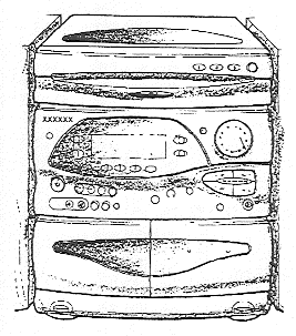
Within Philips Audio - Vienna, a new audio set was being developed (figure 1). Although the set was derived from an earlier set, changes in the architecture made it unclear if the modules in the set would satisfy the thermal criteria.
1.2 Goal
The goal of a project at CFT was to predict the thermal behaviour of the set, using Flotherm, and to check if the modules in the set would satisfy the thermal criteria. The main demands were that the first results should be available within 2 weeks and that simulation results should have a known accuracy. A known accuracy would enable safe conclusions regarding the thermal requirements.

Figure 1 - The audio set which had to be checked on thermal criteria.
1.3 Approach
To deal with the demands of Audio - Vienna, the following approach was chosen.
-
A library was created of compact models, representing the key-modules of the set. The compact models are able to predict useful thermal parameters. The housing of the set was also included in the library.
-
A system model was assembled, from the library, of the predecessor of the current set. The accuracy of the simulation results was estimated by a parameter study. The results were validated by comparing to previous temperature measurements on the predecessor.
-
A system model was made of the current set. Different user situations were simulated and specified criteria were compared to simulation results. Conclusions were drawn based only on simulation results
-
To check if the estimation of the accuracy was correct, the simulation results were also compared to measurements at the end of the project.
Aspects of the given approach are discussed in this paper.
2 Library of compact models
2.1 Introduction
A library of compact models was made, using Flogate. The compact models, representing key-modules, are simplified models of these modules. They should be able to correctly predict the specified thermal parameter. The set-up of such a library was chosen for several reasons:
-
It enables a structured validation of the key-module models.
-
The compact models of frequently used key-modules can easily be used for building system models of new sets.
-
Building a system model of the complete set out of a series of compact models is expected to introduce less modelling errors.
The guidelines to build the compact models are shortly described. One of the compact models (VCD module) is discussed in more detail.
2.2 Guidelines
The compact models of key-modules are made according to the following guidelines:
-
Only those parts of modules are modelled which are obstructing the air flow or are representing an important thermal resistance
-
Components are not modelled unless they are an essential obstruction for the air flow. Dissipations are put into larger module parts or PCB's
-
Module parts are modelled as conducting cuboids or internal plates. Plates are used if the conduction in the plane is not influencing the "measured" temperatures.
-
Key-points are used for all co-ordinates. Not defining key-points would increase the possible introduction of errors.
-
The material properties (conductivities) are coarsely estimated: the conductivities are: plastic parts - 0.2 W/mK, metal parts - 50 W/mK, components - 200 W/mK (for one modelled component), single layer PCB - I W/mK, for multi-layer PCB's a thermal tool is used for estimating the conductivity [Dean], VCD blocks - 5 W/mK (derived from comparison with full model).
-
Thermal criteria consist of mean temperatures of PCB's or non dissipating blocks. The relation between critical component temperatures, not present in the compact model and those larger parts which are present in the compact models is calculated by using a Thermal Tool which contains analytical/empirical relations or by using full (detailed) models.
-
The heatsink of the power module, placed at the outside of the set, is replaced by a plane with an increased heat transfer coefficient. The value of this heat transfer coefficient is calculated by using The Thermal Tools. In this toolset a calculation tool is available, containing empirical relations for the heat transfer coefficient of parallel fins, including the effect of flow heating.
-
The air slots in the housing are modelled as vents with a loss factor of2 (based on device velocity). This value shows to be incorrect for velocities in the order of 0.1 m/s (in case of free convection). However, in the most critical use of the set, a fan is extracting air from the set and the pressure drop over the air slots is negligible, compared to the maximum fan pressure. In that case the loss factor is of no importance.
It was not possible in the short time available to create an accurate compact model of the trafo. Main problems were the unknown distribution of the dissipated power over the primary coil, secondary coil and the core, and the anisotropic conductivity of the coils.
2.3 The VCD module
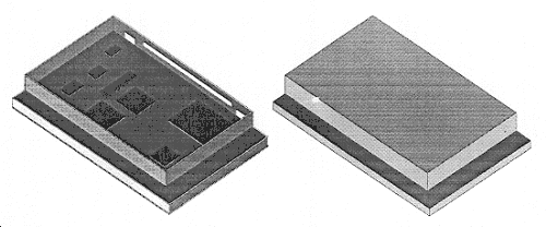
One of the key-modules is a VCD module (figure 2). The module consists of a metal casing, containing a PCB. This module's original thermal specification was a maximum ambient temperature. Although maximum ambient temperatures are commonly used as thermal specifications of electronic devices, it will be clear to thermal engineers that this specification is quite useless. Firstly, the ambient temperature does not exist. Secondly, the relation between ambient temperatures and the temperatures of temperature critical components inside the casing depends on the application of the VCD module in a set. The application will influence the thermal resistance from components to the ambient of the VCD module and therefore, will influence the temperature difference.

Figure 2 Full model (left) and compact model of the Videam2 module.
To create and validate a compact model of the VCD module, first a full model was made. The full model contained the PCB with components. and the metal casing, including some air slots. The compact model consisted of two cuboids (=5W/mK) both dissipating half of the total dissipation (figure 2).
Both models were used in several simulations with realistic boundary conditions, possibly present in sets. (both forced and free convection with and without conduction to a carrier) Both models showed the same casing temperatures for these applications. Differences remained within 3C. The different boundary conditions also showed that the temperature difference between the casing (almost uniform temperature) and the components were not a function of the boundary conditions outside the metal casing, even though there were some air slots in the metal casing. Therefore, it was advised to use a maximum metal casing temperature as thermal specification.
Due to simulation results, this new thermal specification for the VCD was chosen which has several advantages:
-
There is a clear relation between the metal case temperature and the critical component temperatures
-
The case temperature is hardly varying over the surfaces and therefore, can be specified as one value.
-
The case temperature can be easily measured in contrast with an air temperature. Moreover, the exact position is not really of interest.
-
The simulations (and later on measurements) showed that the value of the specified maximum case temperature could be equal to the previously defined maximum ambient air temperature. The application in the current set showed a mean air temperature in the order of 10C lower than the casing temperature. This means that the VCD module can be applied in much more extreme conditions than previously thought.
3 The system model of the Audio set 3.1 Introduction
The system model was set up for both the predecessor of the current set and the current set. It consists of a series of compact models, created in a similar way as the previously described VCD module. For critical parts temperature criteria are defined on the level of PCB's or module parts. For the power module, as an exception, the power amplifier was modelled and specified. This component was directly placed against the heatsink and was believed to be modelled sufficiently accurate. The system model of the current set is shown in figure 3.

Figure 3 The set up of the system model of the audio set.
The set was constructed of a library of compact models.
3.2 Guidelines
The system model was constructed out of the compact models. The following guidelines were used to complete the model:
-
The contacts between key-modules (e.g. housing and trafo) are modelled as planar resistance's with a thermal resistance, simulating the thermal resistance of the actual contact.
-
At the bottom of the set an isolated surface was modelled, together with vents, simulating the air slits beneath the set.
-
On the external boundaries, a heat transfer coefficient of 10 W/m2K is used.
-
The simulations are carried out with:
-
An ambient temperature of 35C, specified as being the maximum ambient temperature.
-
Solving conservation of continuity, momentum and enthalpy. Density is assumed to be constant. The Boussinesq approximation is used for calculation of the Buoyancy force. Gravity is set to 9.8 m/s2.
-
No modelling of radiation.
-
Extra grid cells are introduced, creating cells with dimensions in the order of 5 x 5 x 5 mm. These cell sizes are too large to model correct boundary layers. The introduced error is examined in the next section.
3.3 Validation & accuracy
To validate the system model and to retrieve some indication on the accuracy of simulated temperatures, the accuracy of the simulation results was estimated by carrying out a parameter study on a system model of the predecessor of the current set. Calculations carried out with this model were compared to available temperature measurements.
For the parameter study, first, the main causes were defined which are believed to influence the accuracy of simulated temperatures. These causes cover input information, numerical modelling and geometrical simplifications. A parameter was defined together with a range over which they are believed to vary with a 95% certainty. The parameters which showed to be the most influencing are shown in table 1, together with the expected range.
|
Parameter |
Variation of parameter |
|
heat dissipation of components |
-20% - +20% |
|
fan airflow/heat transfer from heatsink to air |
-20% - +20% |
|
thermal resistance of modules/PCB's to local ambient air |
-50% - 0% |
|
flow direction through side air slots in housing1 |
perpendicular plane - 45 directed downwards |
Table 1 Main parameters and the 95% range over which they are believed to vary.
The air slots used in the housing are modelled as vents which have a default inflow direction which is perpendicular to the plane. In this case the air is extracted at the bottom of the set and the air slots consist of vertical slits. Therefore, the inflow direction is likely to be directed to the extracting fan.
The effect of the coarse grid and the absence of radiation modelling was estimated by varying the numerical heat transfer coefficient on dissipating objects (thermal resistance to local ambient air).
The parameters were varied to check the effect on the simulated temperatures. The ranges and simulation results were being dealt with assuming normal distributions. The 95% ranges (2) of the simulated temperatures were derived by varying the paranteters over their 95% range or by estimating the effect. The results for the expected accuracy is shown in table 2.
|
Modules |
Tuner PCB/Heatsink Base |
STK-base |
Tapedeck/Tape-Karaoke, AF-PCB |
CD-PCB/Videam2-case |
|
accuracy of simulated temperatures (C) |
11 |
13 |
3 |
7 |
Table 2 Estimated accuracy of simulated temperature values for the system model of the audio sets.
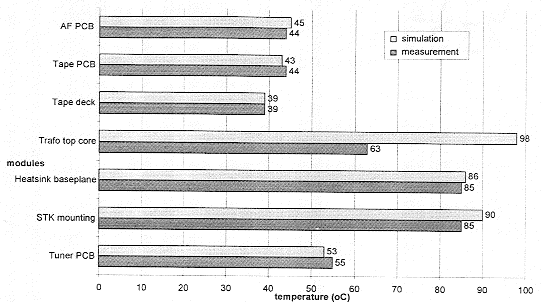
The simulation results were compared with measurements. In the first comparison it was clear that the heat transfer at the heatsink, by forced convection, was underestimated. The results were fined, only by increasing the heat transfer from the heatsink within the specified range of 20%. The final result shows simulated and measured temperatures which agree quite well (except for the trafo). Some of the measured temperatures and simulated temperatures are shown in figure 4.

Figure 4 Simulation results and measurement results for some modules of the
predecessor of the currently developed set (35C ambient).
From this validation it was concluded that a model of the current set could be constructed and that the accuracy shown in table 2, should be taken into account. However, the accuracy is expected to be higher due to the fact that we were able to "fit" the model to a comparable set.
3.4 Results and discussion
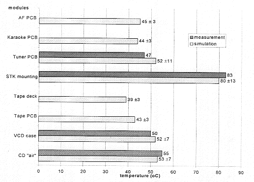
The results from the simulations of the current set are shown in figure 5. Later on measurements were carried out after a prototype had been developed. These measurements were meant for extra validation of the working method, applied for this system model (also see figure 5).

Figure 5 Simulated and measured temperatures for several key-modules in the audio set. Measurements were
carried out later when a prototype was available, for extra validation of the system model
The simulation results, taking into account the accuracy shown in table 1, were compared to the required maximum temperatures. The comparison showed that the modules would satisfy their thermal specifications. Only on the level of the CD the accuracy of the simulation made it impossible to draw conclusions. Only after taking measurements it was concluded that the CD was within specification. Mind that measurements also have their inaccuracy which is not shown here but is considered in the analysis of the results.
The created model was also used to analyse more applications of the set and to find possible improvements. Although these simulations showed interesting results, they are not included in this paper.
The simulation results show quite well agreement with the measurements, although the "fitting" caused much more accurate results than could be expected from the estimated simulation accuracy (table 1).
4. Conclusions
The first results of the simulation were available within two week after start of the project. At that stage it was concluded that the key-modules would satisfy thermal requirements. Only for the CD no safe conclusions could be drawn.
In some cases, especially the VCD, the thermal requirements were redefined, using detailed models of key-modules. These new thermal requirements showed a better relation to critical components. In case of the VCD the redefinition caused that the maximum allowable temperature was effectively increased. It showed that the VCD was not critical and moreover, the specified temperature could easily be measured.
The project showed that, although lots of uncertainties are present when system models are used in an early stage of the design, simulation results enabled a thermal analysis of key-modules. The estimation of the accuracy made it possible to draw better conclusions.
Literature
[1] Dean, Thermal design of electronic circuit boards and packages. Electrochemical Publications, 1985.
[2] Idelchick, I.E.; Flow resistance. A design guide for engineers. Hemisphere, 1989.
[3] Kreith, F; Bohn, M.S.; Principles of heat transfer. West Publishing Company, 1993.
[4] Patankar, S.V.; Numerical heat transfer and fluid flow. Hemisphere, 1980.
[5] Flotherm reference manual version 1.4. Flomerics, 1993.
|

