GE Plastics使用Micro-Stripes软件建模分析蓝牙天线
日期:2012-06-19
| BluetoothTM Antenna Modeling Using MicroStripes | ||||
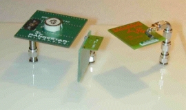
The BluetoothTM standard requires an actual sensitivity of -70dBm at 10m away from the antenna. Taking into account the radio budget and propagation loss over a 10m range, a maximum of 9.95 dB can be lost in the transmitting and receiving antennas. In this application note, we discuss the MicroStripes simulation of a BluetoothTM antenna and specifically the effect of a sheet of engineering thermoplastic material (GE Plastics Cycoloy?/SUP> Resin) just touching the top of the antenna. Various antenna designs were simulated, but in this application note we will focus on the Rangestar?/SUP> 100930 that is a tab mounted embedded BluetoothTM antenna. The 100930 has a peak gain > 4dBi, VSWR < 2.6:1, linear polarization and an enhanced hemispherical pattern which improves the RF link reliability of portable devices. The operational frequency is 2400 to 2483.5 MHz.
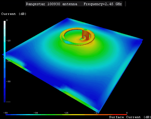
The MicroStripes model includes a stripline feed in FR4 transitioning into the antenna element. The element consists of a metal ring 16mm in diameter mounted on a 6mm high dielectric cylinder having er=3. The material properties for the Cycoloy?/SUP> material are a function of the colorants and additives within the resin, for this case the properties are er=2.7 and tand=0.0045.
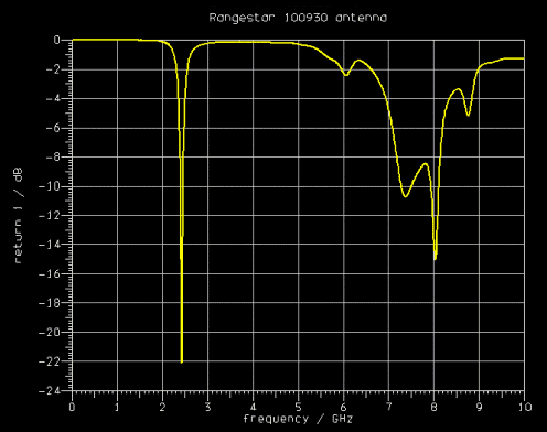
The simulated return-loss for the antenna in free-space, shows a match of 22dB centered around 2.428 GHz. Higher order resonant behavior is seen in the response above 7GHz.
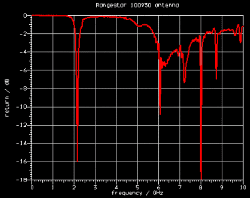
Next we introduce the plastic material which has electrical properties er=2.7 and tand=0.0045 at 2.4 GHz. The material is 3mm thick and touches the top of the antenna. The MicroStripes simulation shows a shift in frequency of -270 MHz and increased reflection into the input port of 6dB.
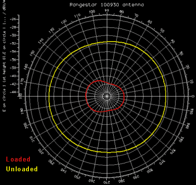
MicroStripes Version 6.0 features a near-field cylindrical scan capability, which enables the azimuth field to be predicted at specific distances away from the antenna. MicroStripes encapsulates the antenna with an equivalent surface in the near-field region and then integrates the electric and magnetic currents over the surface to the required distance. This enables the radiation to be found at 10m without having to solve the electromagnetic fields in the space between. In the plot below, we compare the radiated power at 10m in the azimuth plane, with and without the plastic loading.
The polar plot shows a 10dB reduction in radiated power when the plastic material is introduced. This is severe enough to put the RF performance of the system out of the BluetoothTM requirements.
Conclusions In order to accurately model a devise such as this from a system level standpoint, all material properties must be known, including the enclosure material. The dielectric properties for engineering thermoplastics commonly used for the enclosure are a function of many things including frequency, colorants, and additives. Dielectric material properties for engineering thermoplastics can be obtained from GE Plastics. |





 沪公网安备 31010602003953号