|
Tellabs Inc. is an Illinois-based manufacturer of telecommunications equipment. Tony Kordyban, Senior Thermal Analyst at Tellabs, writes:
The Chip Design Department at Tellabs wanted to stuff a 2.8 watt die (Codename "Viper") into a 14x20mm Plastic Quad Flat Pack (PQFP) and asked, "Can we maintain the maximum allowable case temperature of 85°C in natural convection at 50°C ambient?"
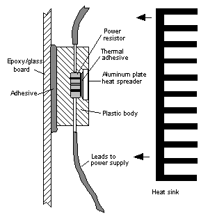
It was obvious from the start that a substantial heat sink would be required. The question was, how big must the heat sink be? Real Viper chips were not yet available, so simple mock-ups of the Viper were built and tested with every heat sink at hand (see Figure 1).

Figure 1 - Test fixture with simplified physical model of Viper chip.
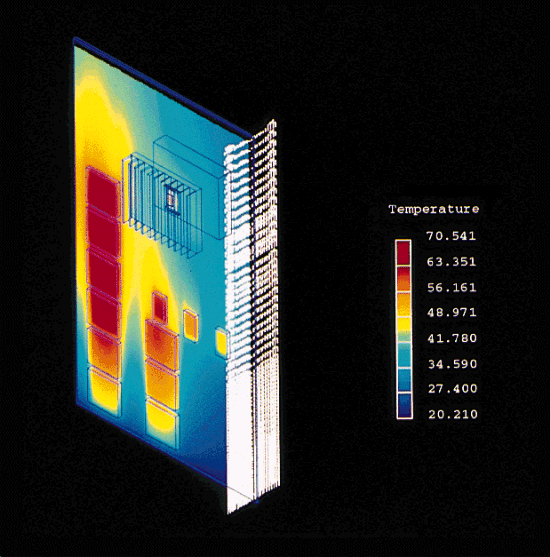
In parallel with the experiments, FLOTHERM simulations were run with the idea of finding the optimum heat sink size.

Figure 2. FLOTHERM model of Viper chip used in a challenging new board design.
The first FLOTHERM simulations produced results which were quite different to the measurements. Further investigation revealed that:
-
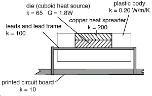
The assumption that all of the heat from the resistor would come out through the top surface via the heat spreader was not correct. In fact, with no heat sink or small heat sinks as much as 75% of the heat passed via "leakage" paths (leads, wires and bottom side of the part).
-
A downdraft of around 0.3m/s from the air conditioning vent in the ceiling above the laboratory bench (easily overlooked) could have a significant effect on temperature measurement.
-
Radiation was shown to have a small effect and could be ignored in this situation.
The above assumptions and errors, if not identified by simulation, could easily have led to a bad choice of heat sink.

Figure 3. FLOTHERM model of test fixture
Even after real Vipers were available for testing, FLOTHERM continued to be useful. The model of the Viper package was used to predict temperatures under conditions that could not easily be produced in the lab. For example, the nominal chip power is only 1.8 watts, but this could vary from chip to chip up to a maximum of 2.8 watts. The synergy of testing combined with simulation made it possible to do two things with relatively little risk:
1) establish the feasibility of Viper early in the project; and
2) predict the thermal performance of Viper on the many different boards where it was intended to be used.
At the end of the Viper project, Tony Kordyban concluded:
FLOTHERM should be considered as another piece of essential thermal laboratory test equipment. Simulation calculates the airflow and temperature at every point in the model, even if you are only interested in the temperature of one component. Often, that helps you discover things you weren't even looking for. In addition to being used when the project is still at the blackboard-and-chalk-dust stage, simulation can be used to increase the value of the experimental data produced by traditional test equipment (thermocouples and anemometers). Simultaneous measurement and simulation of a test fixture provide far more information than either one alone, by:
-
identifying sources of experimental error and estimating their size,
-
extrapolating test data to situations that cannot be reproduced in the lab (such as higher power dissipation)
-
taking component models that were verified experimentally on one board, and predicting their performance on other boards
Thermal simulation is no longer an academic luxury, but is an integral part of the process of predicting and measuring the thermal performance of electronic products.
|

