一个斜向气流中的针状散热器
日期:2012-06-19
A Pin-Fin Heatsink in an Angled Flow |
|
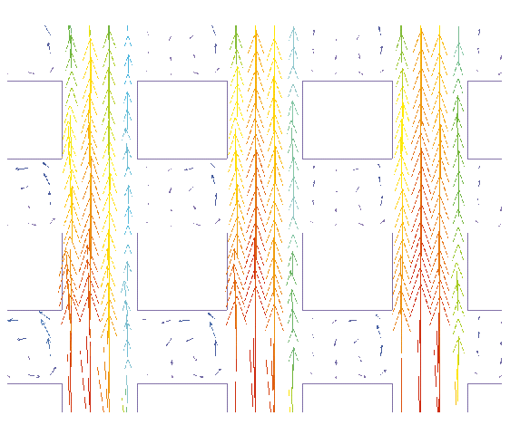
The FLOTHERM software is used at Wakefield for applications where heat conduction or air flow patterns are sufficiently complex that they cannot be modeled using existing empirical methods. One such application is a pin-fin heat sink situated within an angled flow field. A big selling point for pin-fin heat sinks is that they are said to be omni-directional. That is, the heat loss from the heat sink is supposed to be constant for all air flow directions. FLOTHERM was used to investigate the flow dynamics and thermal performance for a standard pin-fin heat sink at various approach flow angles from 0° to 45° and at velocities of 1 and 2 m/s.  Figure 1. Velocity vectors with heat sink positioned normal to the oncoming air flow. Figure 1 shows the velocity vectors when the heat sink is positioned normally with respect to the oncoming air flow (the vectors are shown in a plane approximately half-way up the fins). Most of the air travels down the gaps between the rows of fins. Note the recirculation zones behind each fin where there is very little heat dissipation. 
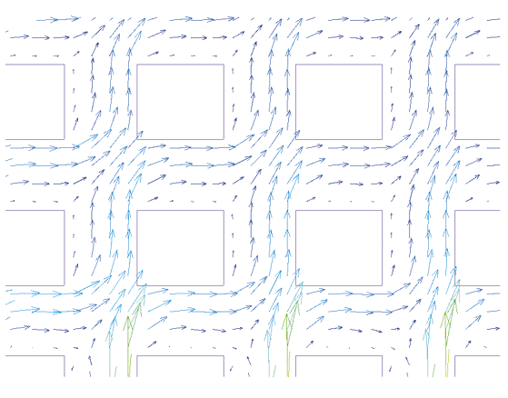
Figure 2. Velocity vectors with oncoming air flow at an approach angle of 30°. Figure 2 shows the air flow patterns for an approach angle of 30°. A greater proportion of air now passes between individual rows of fins. When the approach angle increases to 45° the flow becomes very sinuous through the array of fins (figure 3). However, as the approach angle increases the resistance posed by the heat sink to the flow also increases. Therefore, the total flow rate through the heat sink decreases as more of the approach flow travels into the bypass region on either side of the heat sink. A balance is required between the improved flow distribution diagonally between the fins, and the drop in total flow through the heat sink due to the increased flow resistance.  Figure 3. Velocity vectors with oncoming air flow at an approach angle of 45°.
The overall results for this investigation are shown in figure 4. For both approach velocities (1 and 2 m/s), the most efficient heat transfer is obtained with an approach angle of 0°, when there is fast flow through parallel fin channels. The cooling efficiency decreases slightly with increasing approach angle between 15° and 45°. The significance of this result will depend on the particular application.  Figure 4. Heat sink temperature rise in angled flows. This case demonstrates the usefulness of Computational Fluid Dynamics (CFD) analysis when the flow field is too complex to examine empirically or by spreadsheet methods. The use of FLOTHERM showed why the cooling efficiency changes with respect to flow direction, and quantified the omni-directional performance of this particular pin-fin heat sink. Of course, different values of power dissipation and approach air speed may produce different results. This is why CFD analysis is so useful in new heat sink applications where important questions about the flow field need to be answered. |


 沪公网安备 31010602003953号