风道中卡排布队列对器件测试的影响
日期:2012-06-19
The Effect of Card Mounting Alignment on Component Tests in a Wind Tunnel |
|
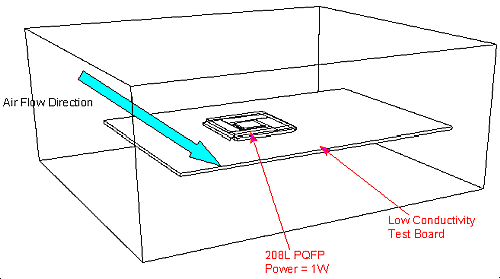
to misalignment of the test card?" The analysis used a 208L PQFP (Plastic Quad Flat Pack) mounted on a low conductivity (JEDEC Standard JESD 51_3) test board in a wind tunnel. This is the same arrangement as has been discussed elsewhere in these Web pages.

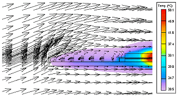
Figure 1: The 208L PQFP in the Wind Tunnel The case was run for a range of incident flow angles from -10 to +10 degrees (negative angles denoting flow coming from above the board and positive angles from below the board). Here are some results for an extreme case: +10 degrees.

Figure 2: Results for +10 degrees of Incidence

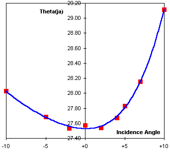
Figure 3: Results for -10 to +10 degrees of Incidence Figure 3 shows the results over the range of incidence tested. The effects of positive incidence (flow from below the card) are considerably greater than the effects of negative incidence (flow from above the card). This is probably due to the formation of a small recirculation region at the leading edge of the board for extreme postive incidence (as shown in Figure 2).
     Incidence Angle   Junction Temp     Theta JA    Diff from
     (degrees)         (degC)            (degC/W)    Datum (%)
          -10             48.03            28.03        1.7%
           -5             47.69            27.69        0.4%
           -2             47.53            27.53       -0.1%
           +0             47.57            27.57        0.0%
           +2             47.54            27.54       -0.1%
           +4             47.67            27.67        0.4%
           +5             47.83            27.83        0.9%
           +7             48.15            28.15        2.1%
          +10             49.11            29.11        5.6%
Table 1: Results for -10 to +10 degrees of Incidence Table 1 lists the predicted values of Theta(ja) as a percentage difference from the datum (zero incidence) case. This shows that, even for the worst case, the error is around 5% and for a practical range of alignment error (+/- 5 degrees) the error is less than 1%.
Author: Steve Addison - Flomerics, San Jose. |


 沪公网安备 31010602003953号